Zone Constitutive Material Models
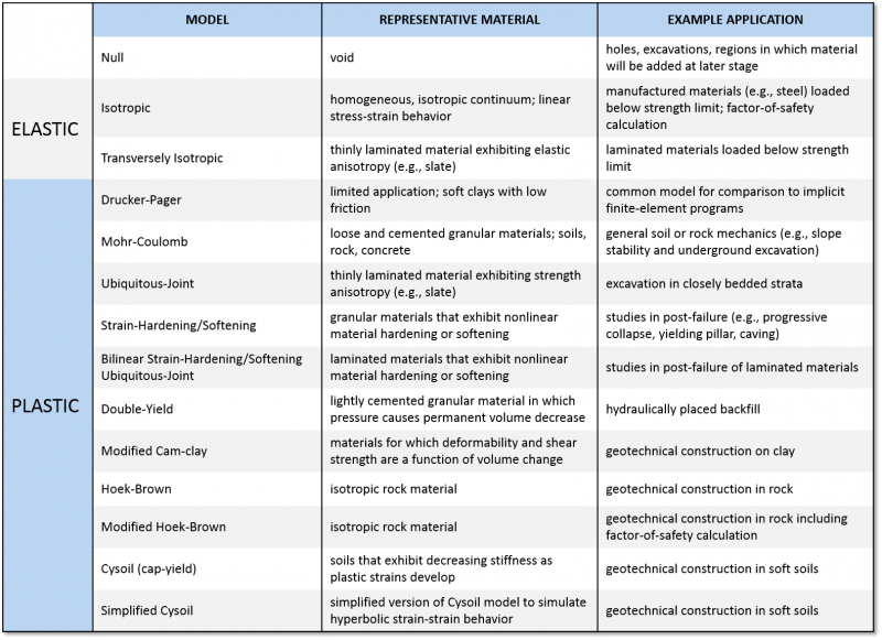
The constitutive models provided in UDEC are arranged into null, elastic and plastic model groups. Input parameters to all of these built-in models can be entered directly as commands, interactively using the GUI or controlled via FISH to modify the behavior of the models.
Null Model
A null material model is used to represent material that is removed or excavated. Since any deformations surrounding any nulled material are tracked, it becomes straight-forward to replace the nulled material with a some other material (e.g., back filling) with an actual material straight-forward, which would not be possible if the material had simply been deleted. Example applications include holes, excavations, regions in which material will be added at a later stage.
Elastic Models
ISOTROPIC - Provides the simplest representation of material behavior. This model is valid for homogeneous, isotropic, continuous materials that exhibit linear stress-strain behavior with no hysteresis on unloading.
TRANSVERSELY ISOTROPIC - Provide the ability to simulate layered elastic media in which there are distinctly different elastic moduli in directions normal and parallel to the layers.
Plastic Models
DRUCKER-PRAGER - May be useful to model soft clays with low friction angles.
MOHR-COULOMB - The conventional model used to represent shear failure in soils and rocks.
UBIQUITOUS-JOINT - An anisotropic plasticity model that includes weak planes of specific orientation embedded in a Mohr-Coulomb solid.
STRAIN-HARDENING/SOFTENING - Allows representation of nonlinear material softening and hardening behavior based on prescribed variations of the Mohr-Coulomb model properties (cohesion, friction, dilation and tensile strength) as functions of the deviatoric plastic strain.
BILINEAR STRAIN-HARDENING/SOFTENING UBIQUITOUS-JOINT - Allows representation of material softening and hardening behavior for the matrix and the weak plane based on prescribed variations of the ubiquitous-joint model properties (cohesion, friction, dilation and tensile strength) as functions of deviatoric and tensile plastic strain. The variation of material strength properties with mean stress can also be taken into account by using the bilinear option.
DOUBLE-YIELD - Intended to represent materials in which there may be significant irreversible compaction in addition to shear yielding, such as hydraulically placed backfill or lightly cemented granular material.
MODIFIED CAM-CLAY - Used to represent materials when the influence of volume change on bulk property and resistance to shear need to be taken into consideration, as in the case of soft clay.
HOEK-BROWN - Characterizes the stress conditions that lead to failure in intact rock and rock masses. The failure surface is nonlinear, and is based on the relation between the major and minor principal stresses. The model incorporates a plasticity flow rule that varies as a function of the confining stress level.
MODIFIED HOEK-BROWN - Provides an alternative to the Hoek-Brown model with a stress-dependent plastic flow rule, described above. The modified model characterizes post-failure plastic flow by simple flow rule choices given in terms of a user-specified dilation angle. This model also contains a tensile strength limit similar to that used by the Mohr-Coulomb model. In addition, a factor-of-safety calculation based on the shear-strength reduction method can be run with the modified Hoek-Brown model.
CYSOIL - The cap-yield soil model provides a comprehensive representation of the nonlinear behavior of soils. The model includes frictional strain-hardening and softening shear behavior, an elliptic volumetric cap with strain-hardening behavior and an elastic modulus function of plastic volumetric strain. The model allows a more realistic representation of the loading/unloading response of soils.
SIMPLIFIED CYSOIL - A simplified version of the Cysoil model. It offers built-in features including a friction-hardening law that uses hyperbolic model parameters as direct input, and a Mohr-Coulomb failure envelope with two built-in dilation laws.
Creep Material Models
There are also several creep (time-dependent) material models available with the creep model option for UDEC.
User-Defined Models
The C++ source codes for all of the above material models are provided in the directory folder “...\UDEC600\PLUGINFILES\MODELS.” With the UDM option, users can modify these models or create their own constitutive models as dynamic link libraries (DLLs).
Joint Constitutive Models
There are currently four standard and one optional joint behavior models available for UDEC.
Coulomb Slip
Only two types of contacts are required to represent a system of blocks: corner-to-corner contacts and edge-to-corner contacts. These are termed “numerical contacts.” Physically, however, edge-to-edge contact is important as it corresponds to the case of a discontinuity closed along its entire length. A physical edge-to-edge contact corresponds to a domain with exactly two numerical contacts with the joint assumed to extend between the two contacts and be divided in half with each half-length supporting its own contact stress. Incremental normal and shear displacements are calculated for each point contact and associated length. In the normal direction, the stress-displacement relation is assumed to be linear and governed by the stiffness. Contacts are assumed to be soft meaning that blocks can overlap and may have a limiting tensile strength. Similarly, in shear the response is controlled by a constant shear stiffness and the shear stress is limited by a combination of cohesive and frictional strength. In addition, joint dilation may occur at the onset of slip (non-elastic sliding) of the joint. Dilation is governed by a specified dilation angle, ψ. The accumulated dilation is generally limited by either a high normal stress level or a large accumulated shear displacement that exceeds some critical displacement value. This limitation on dilation corresponds to the observation that crushing of asperities at high normal stress or large shearing would eventually prevent the joint from dilating.
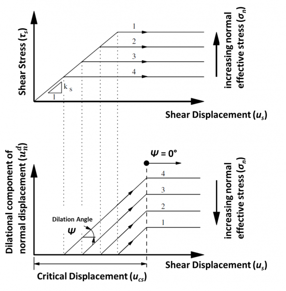
Dilation is a function of the direction of shearing. Dilation increases if the shear displacement increment is in the same direction as the total shear displacement, and decreases if the shear increment is in the opposite direction. The dilation, by default, does not affect the shear strength in UDEC. As an option, the dilation can be included in the effective friction angle for the joint. In this case, the dilation is added to the input friction angle if the shear displacement increment is in the same direction as the total shear displacement, and subtracted if the increment is in the opposite direction. This option can be used to approximate the effect of cyclic shearing on changes in shear strength of a joint.
The Coulomb model can also be adapted to approximate a displacement-weakening response, which is often observed in physical joints. This is accomplished by setting the joint friction, cohesion and tensile strength to reduced values (usually zero) whenever either the tensile or shear strength is exceeded.
Continuously Yielding
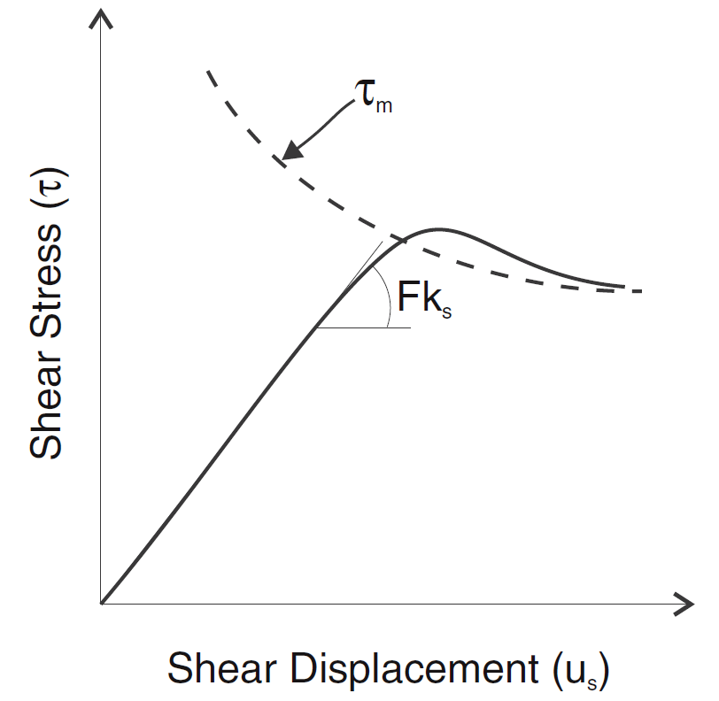
The continuously yielding joint model (Cundall and Hart, 1984) is intended to simulate, in a simple fashion, the internal mechanism of progressive damage of joints under shear. The model also provides continuous hysteretic damping for dynamic simulations by using a “bounding surface” concept similar to that proposed by Dafalias and Herrmann (1982) for soils.
The continuously yielding model is considered more “realistic” than the standard Mohr-Coulomb joint model in that the continuously yielding model attempts to account for some nonlinear behavior observed in physical tests (such as joint shearing damage, normal stiffness dependence on normal stress, and decrease in dilation angle with plastic shear displacement). The essential features of the continuously yielding model include the following.
- The curve of shear stress/shear displacement is always tending toward a “target” shear strength for the joint (i.e., the instantaneous gradient of the curve depends directly on the difference between strength and stress).
- The target shear strength decreases continuously as a function of accumulated plastic displacement (a measure of damage).
- Dilation angle is taken as the difference between the apparent friction angle (determined by the current shear stress and normal stress) and the residual friction angle.
As a consequence of these assumptions, the model exhibits, automatically, the commonly observed peak/residual behavior of rock joints. Also, hysteresis is displayed for unloading and reloading cycles of all strain levels, no matter how small.
Barton-Bandis Joint Model
A series of empirical relations has been developed by Drs. Nick Barton and Stavros Bandis to describe the effects of surface roughness on discontinuity deformation and strength. These relations, known collectively as the Barton-Bandis joint model, have been implemented into UDEC and is optionally available.
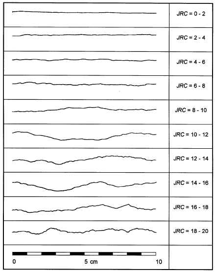
Roughness profiles and corresponding JRC values (after Barton and Choubey 1977).
Joined Contacts
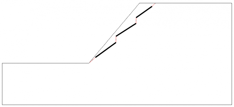
Discontinuities can be created as joined or glued joints and are useful for geometric construction and embedding joints within blocks. Joined contacts cannot slip or open.
UDEC will slave the gridpoints from blocks on either side of a contact. If there are no matching gridpoints, then a special contact constitutive model is used. Properties of the special constitutive model are determined automatically by UDEC. The stiffness of the joined contacts are calculated automatically, but can be modified by the user. The slope includes both joints (black) and joined contacts (red) in order to simulate three en-echelon (or step-path) joints near the rock face.
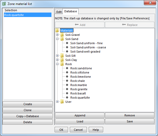
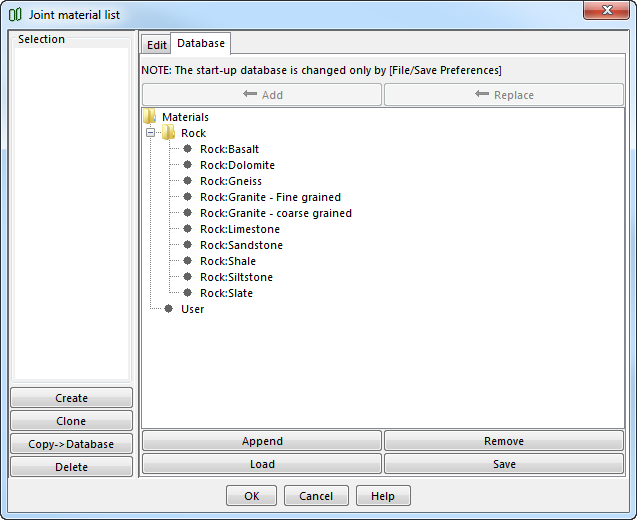
Materials Library
Material models and properties can be assigned for zones and joints directly using commands or interactively via the Material Stage button. With the Zone material list dialog or the Joint material list dialog, the material models and joint models can be defined, respectively. A single zone or joint or a range of these can be interactively selected and defined. A few generic soil and rock materials are provided in the materials libraries; users can save their own property sets and sets can be both exported and imported.