The UDEC user interface provides a complete interactive modeling environment, project management facilities, a built-in library of materials, easy specification of boundary conditions and structural elements, movies, extensive plotting capabilities and run-time monitoring of results.
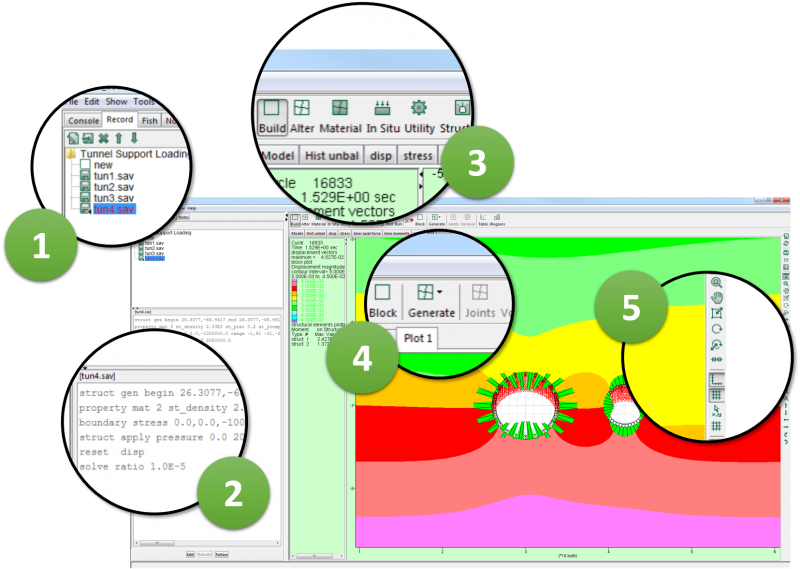
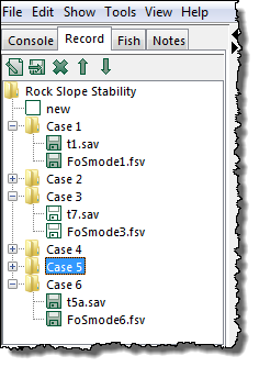
- PROJECT TREE - The model record is in a “project tree” format that shows changes between save files. Save states are displayed in a tree structure.
- RESOURCES PANE - The resources pane contains four tabbed panes with text-based information. A Console pane shows text output and allows command-line input (at the bottom of the pane). A Record pane shows a record of commands needed to generate the current model project state. The record is in a “project tree” format that shows changes between save files. Save states are displayed in a tree structure. The record can be exported to a data file as a set of UDEC commands that represent the problem being analyzed. A FISH pane opens the FISH editor and facilitates execution of FISH functions. Project notes are shown in the Notes pane.
- MODELING STAGES - The stages are arranged in a logical progression for building and solving your model. The left-to-right order follows the recommended procedure for problem solving.
- STAGE TOOLS - When you click on a modeling-stage button, a contextual set of tools that are associated with that stage will become available.
- VIEW TOOLBAR - You can use these tools to manipulate any view pane (e.g., translate or rotate the view, increase or decrease the size of the view, turn on and off the model axes).
Workflow
UDEC is designed to facilitate your workflow by organizing the modeling stages in a logical progression for building and solving your model. As different modeling stages are selected, contextual tools for that stage appear to the right. While this workflow is recommended for problem solving, model conditions can be changed at any point in the solution process by re-selecting a modeling stage.
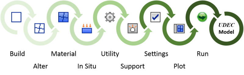
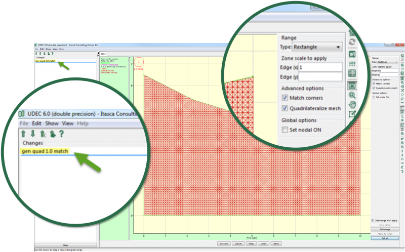
BUILD STAGE - The model geometry is first created by generating blocks and dividing them using jointing.
ALTER STAGE - Blocks can be hidden, making it easier to limit additional sub-jointing to facilitate model generation. For excavations, blocks can be deleted, added or backfilled. Blocks also can be made deformable through finite-difference zoning within each block.
MATERIAL STAGE - Material models and properties are assigned to the blocks and joint structure in the model. Existing joints can be joined together and C++ UDM material models can be loaded.
IN-SITU STAGE - Mechanical, fluid and thermal boundary and initial conditions are applied. Boundary element domains (outside of rock mass) conditions can be specified.
UTILITY STAGE - Provides tools to monitor model variables and access model results.
STRUCTURE STAGE - Provides tools to add or delete structural support elements (cables, liners, beams, etc.) to the model and specify their properties.
SETTINGS STAGE - Allows model global conditions (gravitational constant, damping, time step, etc.) to be set or changed during the analysis.
PLOTTING STAGE - Provides access to all plotting facilities in UDEC including model plot items (zone contours, displacement plots, property values, etc.), table and history charts and moment-thrust diagrams.
RUN STAGE - Set the solution mode (solve or cycle, relax, and FOS) and initiate the model calculations.
Interactive
UDEC is a command-driven program that can be run either interactively or from an ASCII data file. The GUI provides a tool to assist you with the generation of commands using graphical tools interactively.
Project-based
A project file is created when you start a new project. It is an ASCII file containing variables that describe the state of the model and the GUI at the stage when the project is saved and includes a link to the individual UDEC save files associated with the project. The file contains all data and commands associated with the project and is updated automatically every time a new model state is saved.
Project Tree
When using the GUI, saving and restoring problem states is done automatically, and the Project Tree Record format allows the user to switch among the different saved states by point-and-click operations. This is particularly useful for dividing your model into construction stages such as initial equilibrium, excavation sequences, incremental support or different time periods. Additionally, any branch of the tree can be cloned (copied) and used to examine an alternative set of model properties or in-situ conditions for parametric or sensitivity studies.