An important aspect of geomechanical analysis and design is the use of structural support to stabilize a soil or rock mass by using engineered materials to restrict displacements in the immediate vicinity of an opening or excavation. This structural logic has been developed using the same finite-difference algorithms as the rest of the software (as opposed to a matrix-solution approach), allowing the structure to accommodate large displacements and to be used for dynamic as well as static analysis. There are several different types of reinforcement designed to operate effectively in a range of ground conditions. Support is divided in UDEC into two types: (1) reinforcement and (2) surface support.
Reinforcement Support
Reinforcement consists of tendons (i.e., cables or bolts) installed in holes drilled into the ground. Reinforcement acts to conserve inherent rock mass strength so that it becomes self-supporting. Two types of reinforcement models are provided in UDEC: (1) local reinforcement where only the local effect of reinforcement (where it passes through existing discontinuities) are considered and (2) global reinforcement which considers the presence of the reinforcement along its entire length throughout the soil or rock mass.
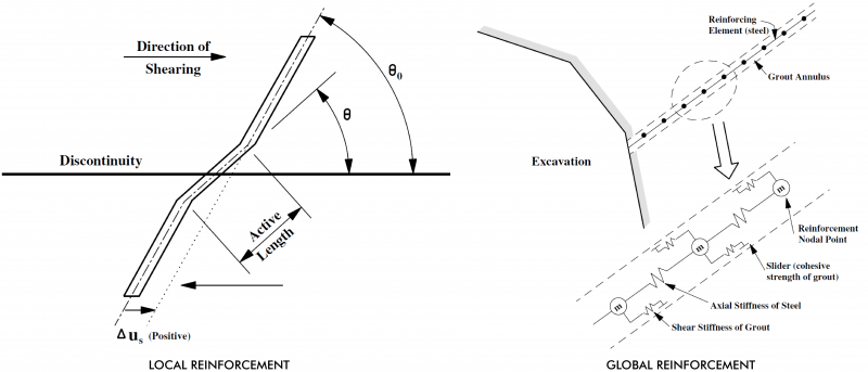
Two types of global reinforcement are provided in UDEC:
CABLE REINFORCEMENT - Provides shear resistance along the cable. Cable elements may also be pre-tensioned in UDEC.
ROCKBOLT REINFORCEMENT- Provides shear resistance along the length of the rockbolt and resistance normal to the length of the bolt, including bending resistance.
Surface Support
Surface supports are placed on the surface of an excavation, and in many cases, act to truly support in whole or in part the weight of individual blocks isolated by discontinuities or zones of loosened rock. Two types of structural elements are available in UDEC:
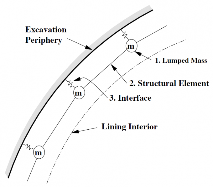
BEAM ELEMENTS - Two-dimensional structural beam elements provide an effective method to include bending effects, which usually cannot be neglected for typically thin surface linings on tunnels and exposed slopes. The structural beam elements can be connected to rigid blocks or deformable blocks and can account for both: (1) slip between support and excavation periphery and (2) large displacements with nonlinear material behavior.
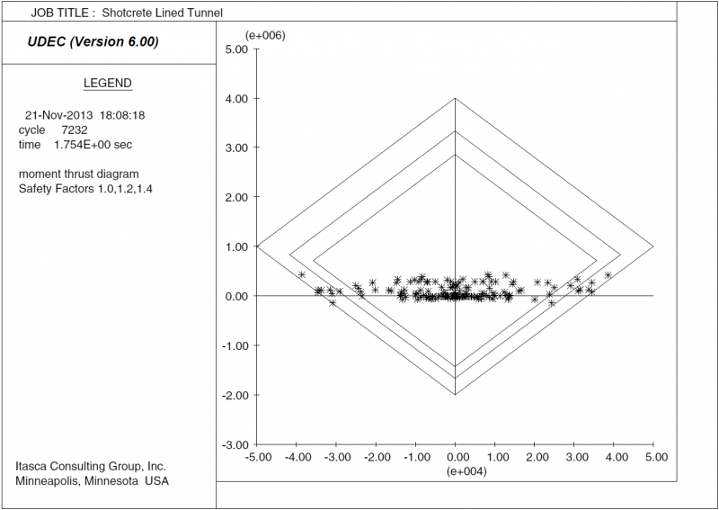
Beam elements include an elastic-plastic material model that incorporates bending resistance, limiting bending moments and yield strengths of the beam material. The material model can simulate inelastic behavior that is representative of common surface-lining materials. This includes materials that behave in a ductile manner (e.g., steel-ribs), as well as non-reinforced and reinforced cementitious materials (such as concrete and shotcrete) that can exhibit either brittle or ductile behavior. Note that shear failure is not included in the material model.
The behavior of the material model can be plotted on a moment-thrust interaction diagram. These diagrams illustrate the maximum force that can be applied to a typical section for various eccentricities and are commonly used in the design of concrete columns. The ultimate failure envelopes for non-reinforced and reinforced cementitious materials are similar. However, reinforced materials have a residual capacity that remains after failure at the ultimate load; whereas non-reinforced cementitious materials typically have no residual capacity. Moment-Thrust yield envelopes can be plotted directly in UDEC.
SUPPORT MEMBERS - One-dimensional support members can be attached to two boundaries of an interior surface. The support member has no independent degrees of freedom, but simply imposes forces on the surfaces to which it is connected. Support members are intended to model hydraulic props, wooden props, sticks or wooden packs that are placed to support an underground opening. A support member may also have a width associated with it; in this case, it behaves as if it were composed of several parallel members spread out over the specified width. The force-displacement behavior can also be made load-rate dependent to simulate several types of support elements used in reef mining (e.g., profile props, yielding props and sticks).
3D Support Effects
Although UDEC is a two-dimensional program, three-dimensional support can be simulated by averaging the effect in three-dimensions over the distance between the elements. Donovan et al. (1984) suggest that linear scaling of material properties is a simple and convenient way of achieving this in the out-of-plane model direction for a regularly spaced pattern. A scaling parameter can be provided for the structural elements to scale properties and account for a spaced pattern of structural elements for reinforcement, cables, rockbolts, beams and supports.