
Six different joint constitutive models are included with 3DEC to provide a range of behaviors. The most basic is the Elastic joint model which is primarily used for model construction joints. The other joint models are intended to represent geological joints or artificial interfaces: the standard being the Mohr-Coulomb model and a more advanced Continuously Yielding model. With the C++ UDM (User-Defined constitutive Models) option, you may create your own joint (and zone) constitutive models to represent new model behavior.
Joint models and properties can be assigned separately to individual, or sets of, discontinuities in a 3DEC model. Note that the geometric roughness of a joint is represented via the joint material model, even though plotted discontinuities are represented as a planar segment.
Elastic Joint Model
The Elastic joint model can be used to simulate construction joints that are required to build model geometries, but do not correspond to real slipping joints or faults. The behavior is governed by the joint normal and shear stiffness; no yielding can occur.
Mohr-Coulomb Joint Model
The basic joint constitutive model incorporated in 3DEC is the generalization of the Mohr-Coulomb strength criterion. This law works in a similar fashion both for sub-contacts between rigid blocks and for sub-contacts between deformable blocks. Both shear and tensile failure are considered, and joint dilation is included.
In the elastic range, the behavior is governed by the joint normal and shear stiffnesses. Once the onset of failure is identified at the sub-contact, in either tension or shear, the tensile strength and cohesion are taken as zero, which approximates the “displacement-weakening” behavior of a joint. Dilation takes place only when the joint is at slip. Actual joints display a reduction in the dilation angle as the residual friction state is approached. In 3DEC, the joints can be prevented from dilating indefinitely by prescribing a limiting shear displacement; when the magnitude of the shear displacement exceeds this limit, the dilation angle is set to zero. Since dilation is a function of the direction of shearing, dilation increases if the shear displacement increment is in the same direction as the total shear displacement and it decreases if the shear increment is in the opposite direction.
Continuously Yielding Joint Model
The continuously yielding model is intended to simulate, in a simple fashion, the internal mechanism of progressive damage of joints under shear. The model also provides continuous hysteretic damping for dynamic simulations by using a “bounding surface” concept. It is considered more “realistic” than the standard Mohr-Coulomb joint model in that the continuously yielding model attempts to account for some nonlinear behavior observed in physical tests (such as joint shearing damage, normal stiffness dependence on normal stress, and decrease in dilation angle with plastic shear displacement). The essential features of the continuously yielding model include the following:
- The curve of shear stress/shear displacement is always tending toward a “target” shear strength for the joint (i.e., the instantaneous gradient of the curve depends directly on the difference between strength and stress).
- The target shear strength decreases continuously as a function of accumulated plastic displacement (a measure of damage).
- Dilation angle is taken as the difference between the apparent friction angle (determined by the current shear stress and normal stress) and the residual friction angle.
As a consequence of these assumptions, the model exhibits, automatically, the commonly observed peak/residual behavior of rock joints. Also, hysteresis is displayed for unloading and reloading cycles of all strain levels, no matter how small.
Softening Healing Mohr-Coulomb Joint Model
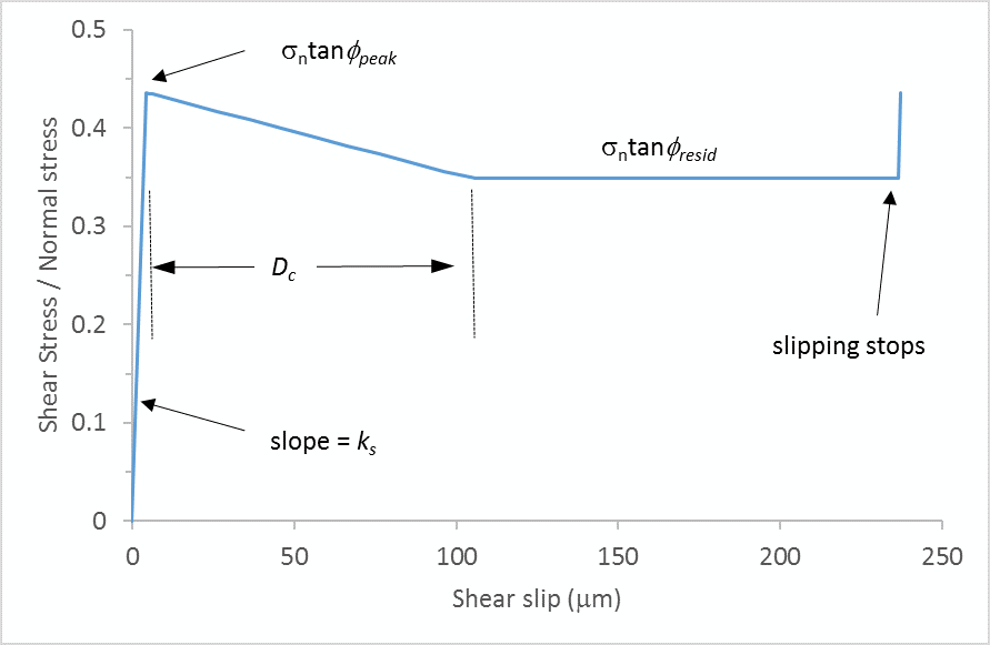
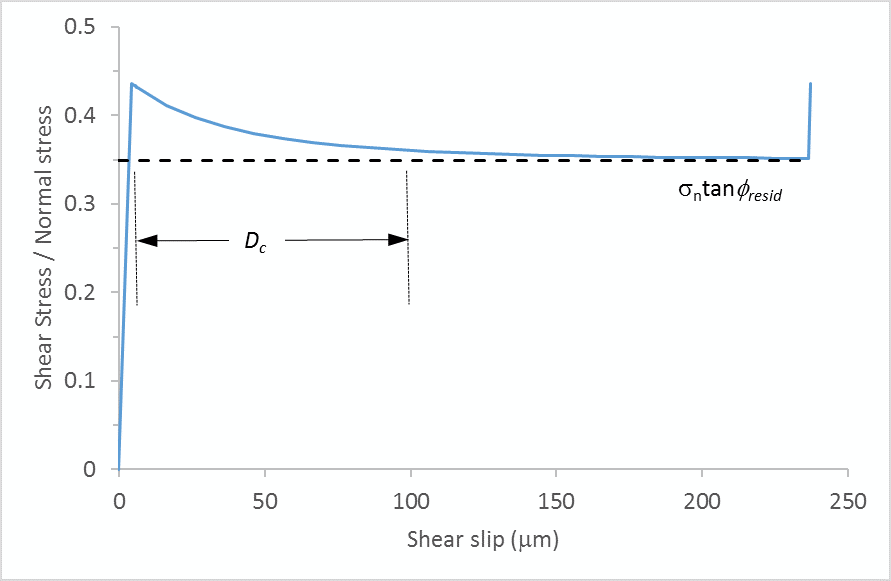
The Softening Healing Mohr-Coulomb model is based on the standard Mohr-Coulomb model with two additions to improve modeling seismicity:
- When the joint starts slipping, the shear strength evolves from the peak value to the residual value over a user-specified critical slip distance Dc. This means that not all slip events are seismic.
- When slipping stops, the shear strength recovers instantaneously to the peak value. This means that joint stick-slip behavior is possible.
Two formulations, linear and non-linear, for the evolution of shear strength are available. For the non-linear formulation, an exponent (α > 1) dictates the severity of the strength drop.
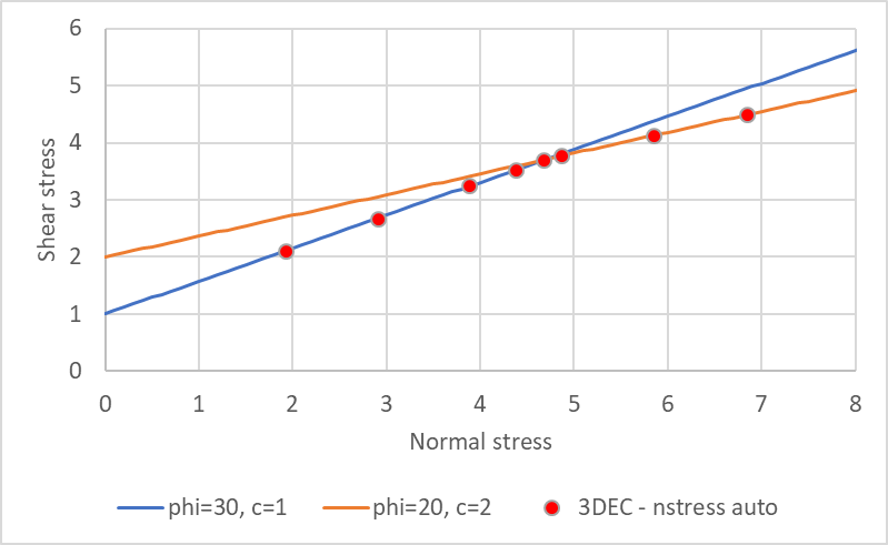
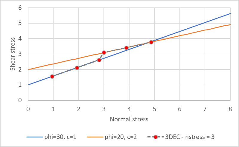
Bilinear Mohr-Coulomb Joint Model
The Bilinear Mohr-Coulomb joint model has two different shear strength envelopes. The failure envelope changes when a critical level of normal stress is exceeded. By default, the normal stress threshold is automatically calculated at the intersection of the two failure envelopes, but the user may override this default and specify any value. Both the peak and residual shear strengths can have bilinear envelopes and there may be different normal stress thresholds for the peak and the residual.
Power Law Creep Joint Model
The creep behavior in a discontinuity is of a different nature depending on the joint surface (planar or rough) and on the filling material (gauge).
- In unfilled discontinuities, two mechanisms can be distinguished depending on the joint surface characteristics: in planar joints, the creep displacement is controlled mainly by an adhesion-frictional mechanism [Bowden and Curran 1984].
- In rough joints, the creep displacement is due to stress concentrations at asperities that cause slip as the asperities yield progressively and the shear stresses are redistributed to other intact asperities [Schwartz and Kolluru 1982, Ladanyi 1993].
- Rock joints may naturally be filled with frictional or cohesive material which is usually of a poor quality. In this case, the creep is controlled mainly by the characteristics of the filling material [Höwing and Kutter 1985, Malan et al. 1998].
To simulate the creep due to the filling material, Itasca has adapted Norton's law, which is commonly used to model the creep behavior of soft rocks subjected to a shear load, for the joint elements. The Power-Law-Creep joint model in 3DEC is characterized by a visco-elasto-plastic behavior in the shear direction and an elasto-plastic behavior in the normal direction. The visco-elastic and plastic elements are assumed to act in series; the visco-elastic behavior corresponds to a Norton’s law; and the plastic behavior corresponds to a Mohr-Coulomb joint model.
C++ UDM Joint Model
This optional feature allows the use of joint constitutive models that are developed and compiled outside of the executable code, written in C++ (using Microsoft Visual Studio 2010) and compiled as a DLL (dynamic link library) file that can be loaded as needed. The main function of the model is to return new forces, given displacement increments. However, the model must also provide other information (such as names) and perform operations such as writing and reading save files.